Posts

Enhance Grid Stability

 Grid stability is crucial for the reliable and efficient operation of an electrical power system. Enhanced grid stability ensures that the system can withstand disturbances, maintain acceptable voltage and frequency levels, and quickly recover from disruptions. Here are several measures to enhance grid stability: 1. **Advanced Monitoring and Control Systems:**    - Implement advanced Supervisory Control and Data Acquisition (SCADA) systems to monitor and control the grid in real-time.    - Utilize synchrophasor technology for high-speed, time-synchronized measurements that provide a more accurate view of the grid's dynamic behavior. 2. **Wide-Area Monitoring Systems (WAMS):**    - Deploy WAMS to enhance situational awareness by collecting and analyzing data from various points across the grid.    - Use wide-area measurements to identify system oscillations, voltage instability, and other dynamic phenomena. 3. **Energy Storage Systems:**    - Integrate energy storage systems (batte

Master Load Frequency Control

 Load Frequency Control (LFC) is a crucial aspect of power system operation that involves maintaining the balance between generation and consumption to ensure system stability and reliability. The primary goal of Load Frequency Control is to regulate the power output of generators in response to changes in load and maintain system frequency within acceptable limits. Here are key aspects and components related to mastering Load Frequency Control: 1. **Objective of Load Frequency Control:**    - **Frequency Regulation:** The main objective is to keep the system frequency within acceptable limits (typically 50 or 60 Hz) despite variations in load and generation.    - **Steady-State and Transient Stability:** LFC also addresses the steady-state and transient stability of the power system. 2. **Components of Load Frequency Control:**    - **Automatic Generation Control (AGC):** AGC is a vital component that adjusts the power output of generators in real-time to match the changing demand. It

Tesla Car

Tesla is a company that specializes in the development and production of electric vehicles, energy storage systems, and solar panels.  Their electric cars are highly advanced and feature technology such as self-driving capabilities and the ability to receive software updates remotely.  Tesla has released a number of models of electric cars, including the Roadster, Model S, Model 3, Model X, and Model Y, and is also working on creating a semi-truck and pickup truck.  The company aims to promote the use of sustainable energy and decrease reliance on fossil fuels. Tesla made several advancements in their electric car technology.  Some examples include the introduction of Autopilot, a suite of features that helps drivers with steering, braking, and acceleration on the highway in 2015, the release of the more affordable Model 3 designed for the mass market in 2016, the release of the Model X 100D, a version of the Model X SUV with a longer range, in 2017, the release of the sportier Model 3

Understanding of ohm's law, KVL and KCL

  Ohm's law is a fundamental principle in electrical engineering that describes the relationship between the current, voltage, and resistance in an electrical circuit. It states that the current through a conductor between two points is directly proportional to the voltage across the two points, and inversely proportional to the resistance between them. Mathematically, it can be expressed as: I = V/R Where I is the current, V is the voltage, and R is the resistance. Kirchhoff's voltage law (KVL) is another fundamental principle in electrical engineering that describes the relationship between the voltages in an electrical circuit. It states that the sum of the voltage drops around a closed loop in a circuit is equal to zero. Mathematically, it can be expressed as: ΣV = 0 Where ΣV is the sum of the voltage drops around the loop. Kirchhoff's current law (KCL) is another fundamental principle in electrical engineering that describes the relationship between the cur

Understanding of impedance, admittance, active power, reactive power, apparent power, average power, instantaneous power, and power factor

  In an alternating current (AC) circuit, the electrical quantities of interest include the impedance, admittance, active power, reactive power, apparent power, complex power, average power, instantaneous power, and power factor. Impedance is a measure of the opposition to the flow of AC current in a circuit. It is represented by the symbol Z and is expressed in units of ohms. Impedance is a complex quantity, meaning that it has both a real and an imaginary component. The real component is known as the resistance and the imaginary component is known as the reactance. Admittance is the reciprocal of impedance and is a measure of the ease of AC current flow in a circuit. It is represented by the symbol Y and is expressed in units of siemens. Admittance is also a complex quantity, with a real component known as the conductance and an imaginary component known as the susceptance. Active power is the rate at which electrical energy is transferred in an AC circuit. It is the product of

Understanding of average, rms, peak factor and form factor in ac circuits

  In an alternating current (AC) circuit, the voltage or current can vary periodically over time. There are several ways to describe and quantify the magnitude of these variations, including the average value, root mean square (RMS) value, peak factor, and form factor. The average value of a periodic signal is the average of the signal over one period. For a sinusoidal signal, the average value is equal to zero. The RMS value of a periodic signal is a measure of the effective or DC equivalent value of the signal. It is calculated by taking the square root of the average of the squares of the signal over one period. For a sinusoidal signal, the RMS value is equal to the peak value divided by the square root of 2. The peak factor of a periodic signal is the ratio of the peak value of the signal to the RMS value. It is a measure of the degree of peakiness or flatness of the signal. The form factor of a periodic signal is the ratio of the RMS value to the average value. It is a mea

Understanding of independent and dependent sources

  In an electrical circuit, a source is a device that provides electrical energy to the circuit. Sources can be classified as either independent or dependent. An independent source is a source that can produce an electric potential (voltage) or an electric current without being influenced by the circuit. Examples of independent sources include batteries, generators, and power supplies. A dependent source is a source that produces an electric potential or an electric current based on the voltage or current in the circuit. Examples of dependent sources include transistors and thermocouples. The behavior of a circuit with an independent source is determined by the characteristics of the source and the resistive elements in the circuit. The circuit will operate the same way regardless of the current or voltage in the circuit. The behavior of a circuit with a dependent source is more complex, as the source produces a current or voltage that is dependent on the current or voltage in

Understanding of series and parallel resistors

  In an electrical circuit, resistors can be connected in series or in parallel. The connection determines how the resistors behave and how they affect the current and voltage in the circuit. In a series connection, the resistors are connected end-to-end, so that the current flows through each resistor in turn. In a parallel connection, the resistors are connected side-by-side, so that the current can flow through multiple resistors at the same time. The relationship between the resistance, current, and voltage in a circuit with resistors connected in series is given by Ohm's law: V = IR Where V is the voltage across the resistors, I is the current through the resistors, and R is the total resistance of the circuit. The total resistance of a circuit with resistors connected in series is equal to the sum of the individual resistances: R = R1 + R2 + R3 + ... The relationship between the resistance, current, and voltage in a circuit with resistors connected in parallel i

Principle and procedure to apply Maximum power transfer theorem in electrical circuits

The maximum power transfer theorem states that, in a linear electrical circuit, the power transferred from the source to the load is maximized when the load resistance is equal to the internal resistance of the source. In other words, the power delivered to the load will be at its maximum when the load resistance matches the internal resistance of the source. To use the maximum power transfer theorem to analyze a circuit, you can follow these steps: Identify the source and the load in the circuit. Calculate the internal resistance (Ri) of the source. This is the resistance of the source as seen from the terminals of the circuit, and it may include the resistance of the source itself as well as any other resistances in the circuit. Calculate the load resistance (RL). This is the resistance of the load as seen from the terminals of the circuit. Compare the internal resistance of the source to the load resistance. If they are equal,

Principle and procedure to apply Norton's theorem in electrical circuits

  Norton's theorem is a principle that can be used to simplify the analysis of linear electrical circuits. It states that any linear circuit, no matter how complex, can be represented by a single current source and a single resistor in parallel. This equivalent circuit is known as a Norton equivalent circuit. To use Norton's theorem to analyze a circuit, you can follow these steps: Identify the current source and the resistor that make up the Norton equivalent circuit. Calculate the current (I) of the current source. This is the short-circuit current of the circuit, which is the current that flows through the terminals of the circuit when the voltage across the terminals is zero. Calculate the resistance (R) of the resistor. This is the equivalent resistance of the circuit, which is the resistance measured between the terminals of the circuit when all current sources are replaced with open circuits. Use the Norton equival

Principle and procedure to apply Thevinin's theorem in electrical circuits

  Thévenin's theorem is a principle that can be used to simplify the analysis of linear electrical circuits. It states that any linear circuit, no matter how complex, can be represented by a single voltage source and a single resistor in series. This equivalent circuit is known as a Thévenin equivalent circuit. To use Thévenin's theorem to analyze a circuit, you can follow these steps: Identify the voltage source and the resistor that make up the Thévenin equivalent circuit. Calculate the voltage (V) of the voltage source. This is the open-circuit voltage of the circuit, which is the voltage measured across the terminals of the circuit when no current is flowing. Calculate the resistance (R) of the resistor. This is the equivalent resistance of the circuit, which is the resistance measured between the terminals of the circuit when all voltage sources are replaced with short circuits. Use the Thévenin equivalent circuit to

Principle and procedure to apply superposition theorem in electrical circuits

  The superposition theorem states that in a linear circuit (one in which the relationships between the circuit elements are linear), the response of the circuit to multiple input sources is the sum of the responses of the circuit to each individual input source. In other words, if you have a circuit with multiple input sources, you can find the total response of the circuit by adding up the responses to each input source separately. The superposition theorem is a powerful tool for analyzing and understanding the behavior of linear circuits, as it allows you to break down a complex circuit into smaller, simpler components and analyze them individually. This can make it easier to understand the circuit as a whole and to predict its behavior under different conditions. To use the superposition theorem, you will typically need to follow these steps: Identify the input sources in the circuit. These may include voltage sources, current sources, or other types of inputs.

AC Source Across Series R Circuit

Image
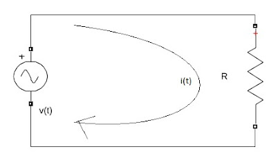
  Let applied voltage in the circuit is v(t)=VmSin(wt). Then current i(t) will flow in the circuit as shown in figure.  R is the resistance of the circuit.  Assume vR(t) is the voltage drop across resistor. According to Ohm's law, vR(t)=R*i(t)                                               i(t)=v(t)/R                    (since vR(t)=v(t))

Nodal Analysis

  Nodal Analysis 1. Nodal analysis can be applied for the planner and non-planner networks 2. Nodal  analysis is based on the application of KCL Note:  1. A principle node is a point where more than two branches are connected. 2. A simple node is a point where two branches are connected. The procedure of nodal analysis: Step 1:   Identify the total no. of principle nodes Step 2:   Assign voltages to each principle node and take one of the nodes as a reference node Step 3:   Develop KCL equations for each node(except for reference node) Step 4:   Solve the KCL equations to get node voltages A special case of nodal analysis(Supernode) A supernode exists in a circuit when two non-reference nodes separated by a pure voltage source The procedure of super nodal analysis: Step 1:   Identify the total no. of principle nodes Step 2:   Assign voltages to each principle node and take one of the nodes as a reference node Step 3:   If super node found, then develop KCL equation for supernode and re

Mesh Analysis

  Mesh Analysis Ø  A mesh is loop which doesn't contain any inner loop Ø  Mesh analysis is only applicable to planner networks Procedure of mesh analysis: Step 1:   Identify the total no. of meshes Step 2:   Assign the mesh currents to each mesh either in anti clock wise or clock wise direction Step 3:   Develop KVL equations for each mesh Step 4:   Solve the KVL equations to get mesh currents Special case of mesh analysis(Super mesh) A super mesh exists in a circuit when two meshes separated by the common current source branch Procedure of super mesh analysis: Step 1:   Identify the total no. of meshes Step 2:   Assign the mesh currents to each mesh either in anti clock wise or clock wise direction Step 3:   If super mesh found, then develop KVL equation for super mesh Step 4:   Develop KCL equation at common current source node. Step 5:   Solve KVL and KCL equations to get mesh currents

Power System Stability

Image
Power System Stability Need for power system stability  What is stability  Different types of stability  Steady-state stability  Transient stability Dynamic stability Classification of stability Development in the field of power systems: Synchrophasor  Smart grid  Renewable energy resource  Facts Plug-in hybrid electric vehicle Flexible Ac transmission system: Facts is power electronic-based system and other static equipment that provide controllability of power flow and voltage Control of power flow in ac system is necessary   FACTS segregated into Variable impedance type   Voltage source converter type Types of fact devices:    

Basic Electrical Part 3


Basic Electrical Part 2


Basic electrical part 1


Practice Session on Mesh Analysis


Parallel Resonance


Series Resonance


IMC based Controller Design for Automatic Generation Control of Multi Area Power System via Simplified Decoupling

https://link.springer.com/article/10.1007/s12555-017-0362-1  

h-Parameter Problem 1

Image
 

Y-Parameter Problem1

Image
 

Z-Parameter Problem

Image